Product Description
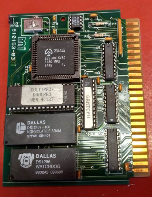
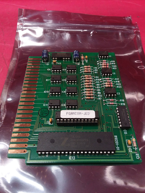
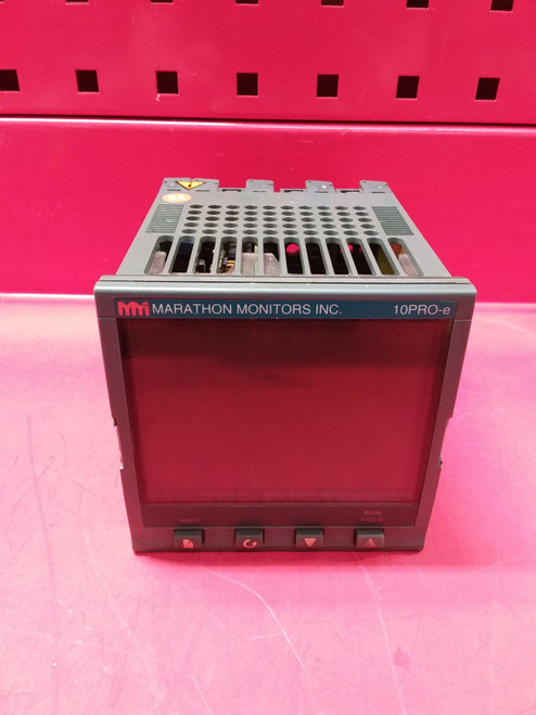
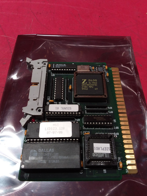
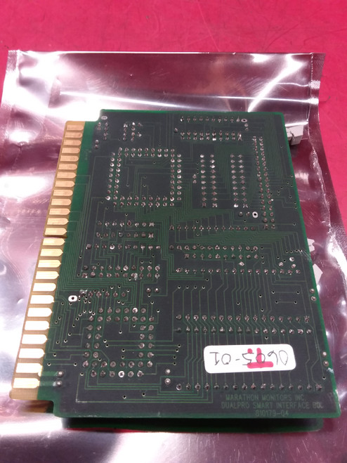
Marathon Monitors FDP123-4.0 DualPro Controller
This unit was in a plant that closed. Tested and cleaned. 30 Day warranty
Tech Data
The MMI DUALPRO Controller/Programmer represents the state of the art in microprocessor-based process control technology. By combining the flexibility of Proportional, Integral, Derivative (PID) control with the features common in programmable controllers, the DUALPRO can tackle even the most complex systems. The following features have been included to allow use of the instrument in many applications:
CONTROL
Is fully site-configurable for single or dual loop control with a variety of simple or complex control variables.
PROGRAMMING
Offers a selectable option that allows programs to be entered and edited in the MMI industry standard Recipe language programmer or the Logic language programmer. This gives the ability to let the operators work with an easy to use procedural program language.
A powerful process/logic programmer that can store up to two-hundred (200) Recipe language programs, consisting of nineteen (19) steps, each, and 200 Logic language programs consisting of twenty-four (24) steps, each. It allows multiple tasks, foreground and background tasks, subroutine calls, test-and-branch capability, and full access to all instrument parameters.
ANALOG INPUTS
The DUALPRO allows for three analog inputs with their individual functions determined by "daughter boards" located on the analog input board inside the unit. The standard connection, at TB D, will have the first input as a thermocouple. The other two inputs are used optionally to input voltage or milliamp signals with a resistor. Up to three (3) fully isolated analog inputs, each separately configurable for thermocouple, RTD, voltage, or current. The total number of inputs can be expanded to 67 inputs with external analog boards.
ANALOG OUTPUTS
Two (2) fully isolated analog output contacts, each separately configurable for voltage or current output, expandable to 18 outputs with external analog board, are provided on TB D and can be adjusted to any upper and lower limit within the ranges given: 0 to 5 V dc or 0 to 22 mA to include the standard settings of 4 to 20 mA or 0 to 5 V dc output. The change from V dc to mA is made through a DIP switch setting on the analog output board. Calibration adjustments are made via on board potentiometers.
ALARM OUTPUTS
Two (2) configurable alarm triacs, assignable as process alarms, deviation alarms, program alarms, or fault alarms.
CONTROL OUTPUTS
Two (2) configurable control output triacs allowing dual control on both loops.
DISCRETE INPUTS and OUTPUTS
Four (4) programmer events, assignable in any combination as either inputs or outputs. This number can be expanded to 68 I/O with external event boards.
COMMUNICATIONS
Four communication ports are at TB C. They use RS-422 / RS485 full or half duplex protocol for all ports. Typically, the HOST port will connect to a host computer; the AUXILIARY port to other instruments; the EVENTS PORT to OPTOMUX I/O devices; and the BASIC TERMINAL PORT to a remote terminal or other programmable device.
PROBE CARE
Automatic probe testing is available and can be initiated during setup by entering the time between tests. Automatic probe burnoff can be setup by entering the time between burnoffs and the time for burnoff. See the specific probe’s documentation for details.


